
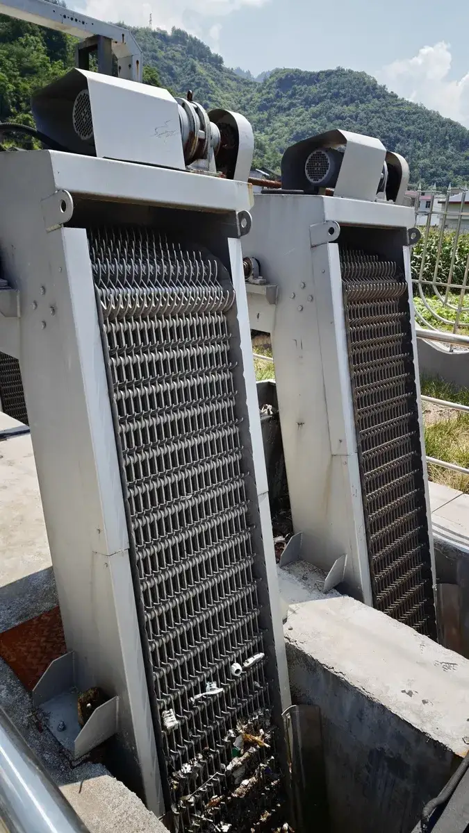
Multi-Rake Bar Screen
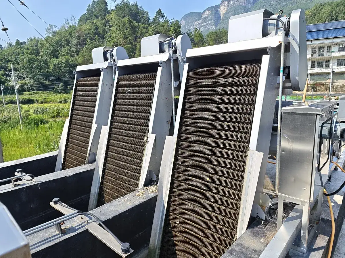
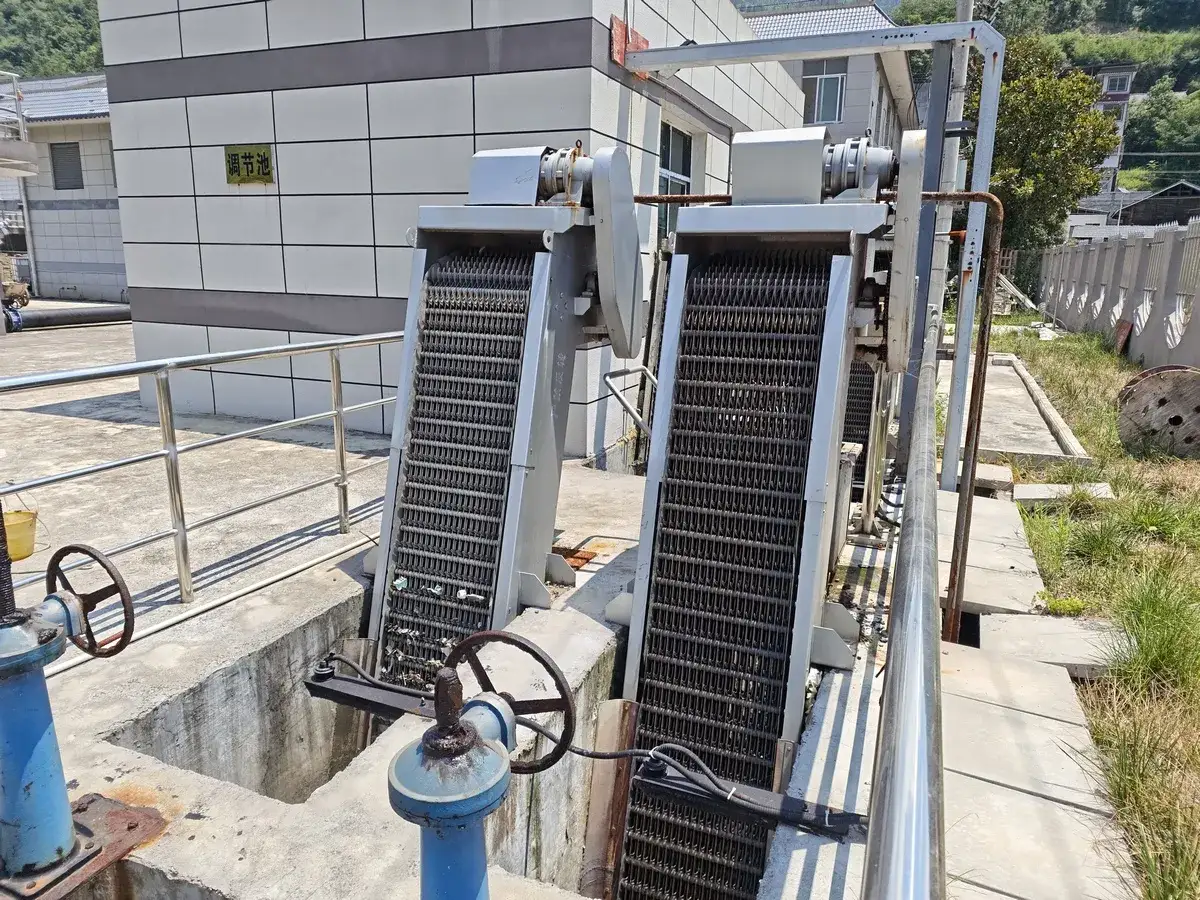
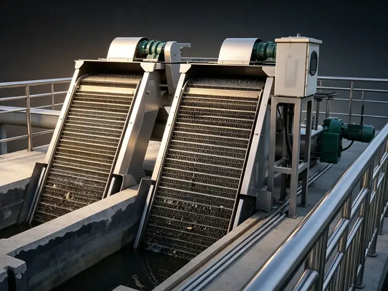
The CF-type multi-rake bar screen is a continuous mechanical screen designed for continuous solid-liquid separation that intercepts solid debris from incoming wastewater. The mechanical bar screen is installed at the inlets of municipal wastewater treatment plants, residential community wastewater pretreatment systems, municipal stormwater and sewage pumping stations, drinking water plants, power plant cooling water systems, etc. It also serves industrial wastewater treatment in textile, dyeing and printing, food processing, pulp and paper, brewing, slaughterhouse, and tannery operations.
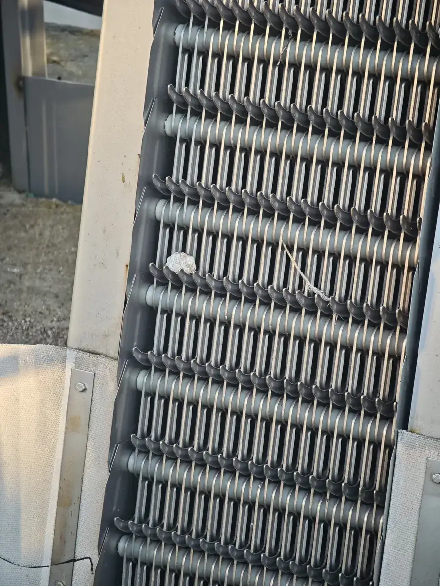
As a solid-liquid separation equipment, the mechanical bar screen uses a rotary rake chain. As wastewater passes through, the rake teeth capture solid debris. The drive unit moves the chain upward, lifting the debris to the top of the bar screen, where it discharges by gravity. The rakes then return for the next cycle, which keeps the screen continuously clear of debris.
| Model | ||||||||||||
| Equipment Width B (mm) | 500 | 600 | 700 | 800 | 900 | 1,000 | 1,100 | 1,200 | 1,300 | 1,400 | 1,500 | |
| Channel Width B₁ (mm) | B + 100 | B + 100 | B + 100 | B + 100 | ||||||||
| Effective Screen Rack Width B₂ (mm) | B – 167 | B – 167 | B – 167 | B – 167 | ||||||||
| Anchor Bolt Spacing B₃ (mm) | B + 200 | B + 200 | B + 200 | B + 200 | ||||||||
| Overall Equipment Width B (mm) | B + 350 | B + 350 | B + 350 | B + 350 | ||||||||
| Rake Tooth Clearance b (mm) | t = 100 | 1 ≤ b ≤ 10 | 1 ≤ b ≤ 10 | 1 ≤ b ≤ 10 | 1 ≤ b ≤ 10 | |||||||
| t = 150 | 10 < b ≤ 50 | 10 < b ≤ 50 | 10 < b ≤ 50 | 10 < b ≤ 50 | ||||||||
| Installation Angle (°) | 60–85 | 60–85 | 60–85 | 60–85 | ||||||||
| Channel Depth H (mm) | 800–12,000 | 800–12,000 | 800–12,000 | 800–12,000 | ||||||||
| Discharge Height Above Platform (mm) | 600–1,200 | 600–1,200 | 600–1,200 | 600–1,200 | ||||||||
| Overall Equipment Height H₂ (mm) | H + H₁ + 1,500 | H + H₁ + 1,500 | H + H₁ + 1,500 | H + H₁ + 1,500 | ||||||||
| Rear Rack Height H₃ (mm) | t = 100 | ≈1,000 | ≈1,000 | ≈1,000 | ≈1,000 | |||||||
| t = 150 | ≈1,100 | ≈1,100 | ≈1,100 | ≈1,100 | ||||||||
| Rake Tooth Speed | ≈2.1 | ≈2.1 | ≈2.1 | ≈2.1 | ||||||||
| Motor Power N (kW) | 0.55–1.1 | 0.75–1.5 | 1.1–2.2 | 1.5–3.0 | ||||||||
| Head Loss | ≤20 (when unobstructed) | ≤20 (when unobstructed) | ≤20 (when unobstructed) | ≤20 (when unobstructed) | ||||||||
| Civil Engineering Load | P₁ (kN) | 20 | 20 | 25 | 25 | |||||||
| P₂ (kN) | 8 | 8 | 10 | 10 | ||||||||
| ΔP (kN) | 1.5 | 1.5 | 2 | 2 | ||||||||
Note: P is calculated at H = 1.5 m. For each additional 1 m of H, total P = P₁ (P₂) + ΔP; t is the rake-chain pitch.
- Direct drive by a cycloidal or helical geared motor, with a compact structure
- Rake teeth and screen openings configured to the flow rate and screening requirement
- Local and remote control, integrated with wastewater treatment equipment
- Mechanical shear pins and overcurrent protection guard against overload
- Parallel configuration available for equipment widths of 1,500 mm and above